Mount A Motor
15 Oct 2019 - Jake Sherwood
motor mount, plan a, b, & zzz
Intro to Fabrication - Mount a Motor - Mobile? / Noise maker Plan ZZZ
The assignment for this week was to mount a motor. My original plan was to make a table top mobile using the cork tops from last weeks assignment.
I faced a slew of hurdles and was forced to go back to the drawing board numerous times. It was almost commical towards the end.
I even failed with my final documentation video. :facepalm: (-‸ლ)
 failed documentation video
Inspiration
My 2 materials project
Zimoun wire noise installation
I was really inspired by the Zimoun example, Ben showed in class, and after scrapping the hanging tops idea, I decided to I would try to embrace the issues I was having and make and piece with sound as well. But it didn’t quite work out that way.
I attempted to use mostly materials I already had, but still had a few Brunos Brunos trips and some Amazon and Tinkersphere orders.
Materials Used:
container store box
acrylic
brass rod/tube
cardboard
TT right angle motor
mini breadboard
9volt battery
various couplers
standoff
gorilla glue
Process:
As mentioned above I wanted to reuse my tops from last week. They ended up being too heavy. The issues with their weight were exacerbated by picking up a flexible shaft couple instead of a ridged one.
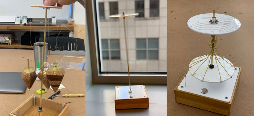
But to take a few steps back, I started by setting up my mock spinner mechanism, sans motor,
 plan a mock up
With that relatively put together, so I thought, I moved on to mounting the motor, power supply, switch, and box cover.
The hardest part here was accounting for the 2 sides of the right angle TT motor. I was only using one but my bracket needed to account for the other side and still allow it to spin.
The TT motor actually has mounting holes, so that helped. But I had to take a bunch of measurements to make sure everything lined up and I could securely mount it and still allow the lower shaft to spin.
To accomplish this I decided to stack 3 levels of material to accommodate the 9.3mm lower shaft.
I opted to just use cardboard as it seemed to function well and I didn’t want to use more of my acrylic supply than I had to.
After measuring a few times I had my illustrator file ready for the laser cutter. I cut out 3 steps for my bracket to give me the height needed.
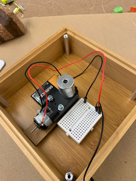
The circuit itself was relatively simple. Just the motor, a 9 volt battery, a switch, and a mini breadboard so I could easily replace the components.
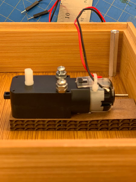
TT motor mounted
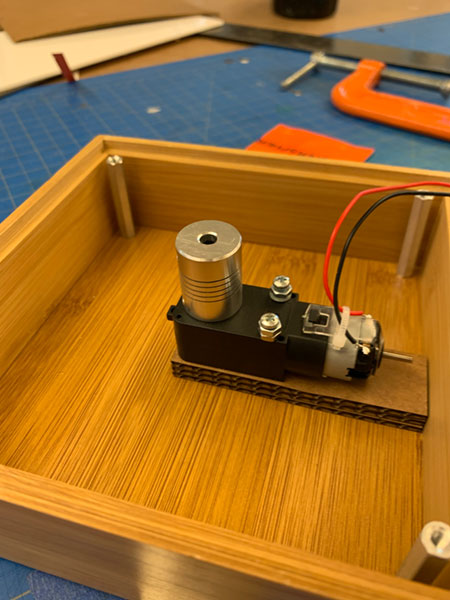
TT motor mounted with coupler
TT motor mounted with circuit
Geting this far provided a few hiccups.
First, the screws I had to mount the motor were a bit too long, to shorten them on the other side, I was using a couple extra nuts under the screw head. One of the screws I was planning to use for mounting wasn’t threaded all the way so I couldn’t postion the nut the same on both screws. I was able to get it sorted by using a couple of washers in place of one of the nuts.
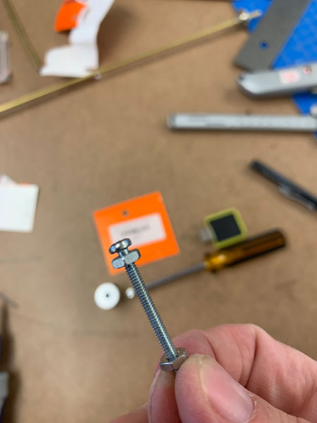
screw not fully threaded
Second, once I had the shaft coupler on, I realized I hadn’t taken the added height into account and I had widen the hole in my acrylic box cover to compensate.
motor circuit works inside box
motor circuit covered
Once I had that all sorted, I was able to loosely put it all together and see that plan A was not going to work as originally envisioned.
Basically they top of my mobile was wobbling all over the place. And the weigh and length of the shaft would require drastic redesign.
So inspired by Zimoun and heeding some of the advice from Ben I started pn plan B.
One piece of advice Ben gave me was to lighten the mounting circle at the top. To do this I basically added some design elements and more mounting points to the top and ran a new laser job.
This gave me a lighter mounting point and I really like the way the design came out.
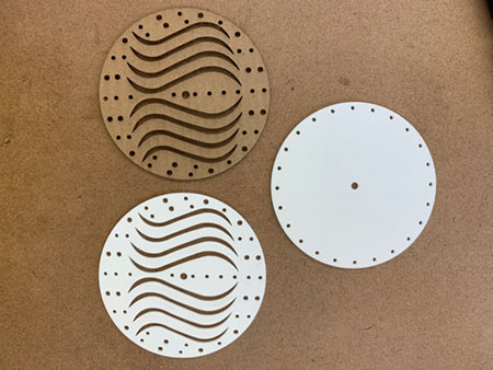
mounting top redesign and prototype
My plan was to hang thin brass rods from the holes. The hope was that they would create and interesting sound as the spun around some hit each other.
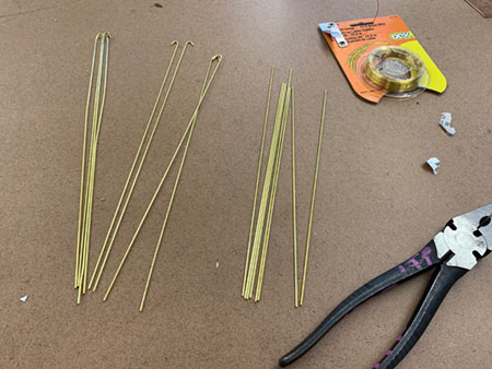
brass rods
This didn’t work out, and they basically all spun outwards and required eye safety to use. I basically created a weapon.
On top of this everything was still wobbling all over the place… danger danger danger.
Amazon to the rescue… I had ordered a couple rigid shaft couplers as a hail mary for Tuesday delivery. They were delivered mid afternoon and I figured I should go home and get them since plan B was also turning out to be a fiasco.
Quick bike ride home and back, I was back at school with a new part that would surely fix all my problems.
Nope…
Shaft coupler was too big to attach to the right angle motor shaft :facepalm: (-‸ლ)
Back to the drawing board.
One other thing Ben had suggested was shorthing the shaft. I had some extra material so I made some shorter shafts. Still wobbled and I wasn’t really getting the sound effects I had hopped for. The brass rods were all swinging out sideways and not hitting each other to create any sound.
I decided to go with a new design where I would us the original mounting top and the brass rods come up from the base and wrap around the center shaft.
I then added a two rods outside the circle to act as “clickers.”
Now spinning the inner structure creates clicks as it connects with the “click” rods.
Final Noise Maker PlanZZZ
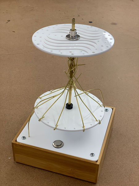
plan z noise maker
Not my original vision and not super proud of how this one turned out. I guess it accomplishes the requirements of the assignment but not my own.
I did learn a lot about sourcing part, shaft couplers dos and don’ts, centrifugal force and how to move on from an original design intent.