Solarbloom
07 May 2021 - Jake Sherwood
 Solarbloom
Solarbloom
My final project for Energy class is Solarbloom - a solar-powered kinetic sculpture.
Inspired by the movement of Japanese paper fans, my previous kinetic flower work, and my mom’s unique glass art, I wanted to create another kinetic sculpture but with a different mechanism.
Mechanism
That different mechanism ended up being one of the most challenging parts of the project.
As soon as I decided on basing the movement on a spin to open, I thought, can I even figure this out?
Many days thinking and researching other mechanisms; I settled on what I call the sequenced tab. I’m sure this has been done before, but I did not find an example precisely like this in my research.
I started with sketching and trying to figure out how to make it spin.
 sketch flower open
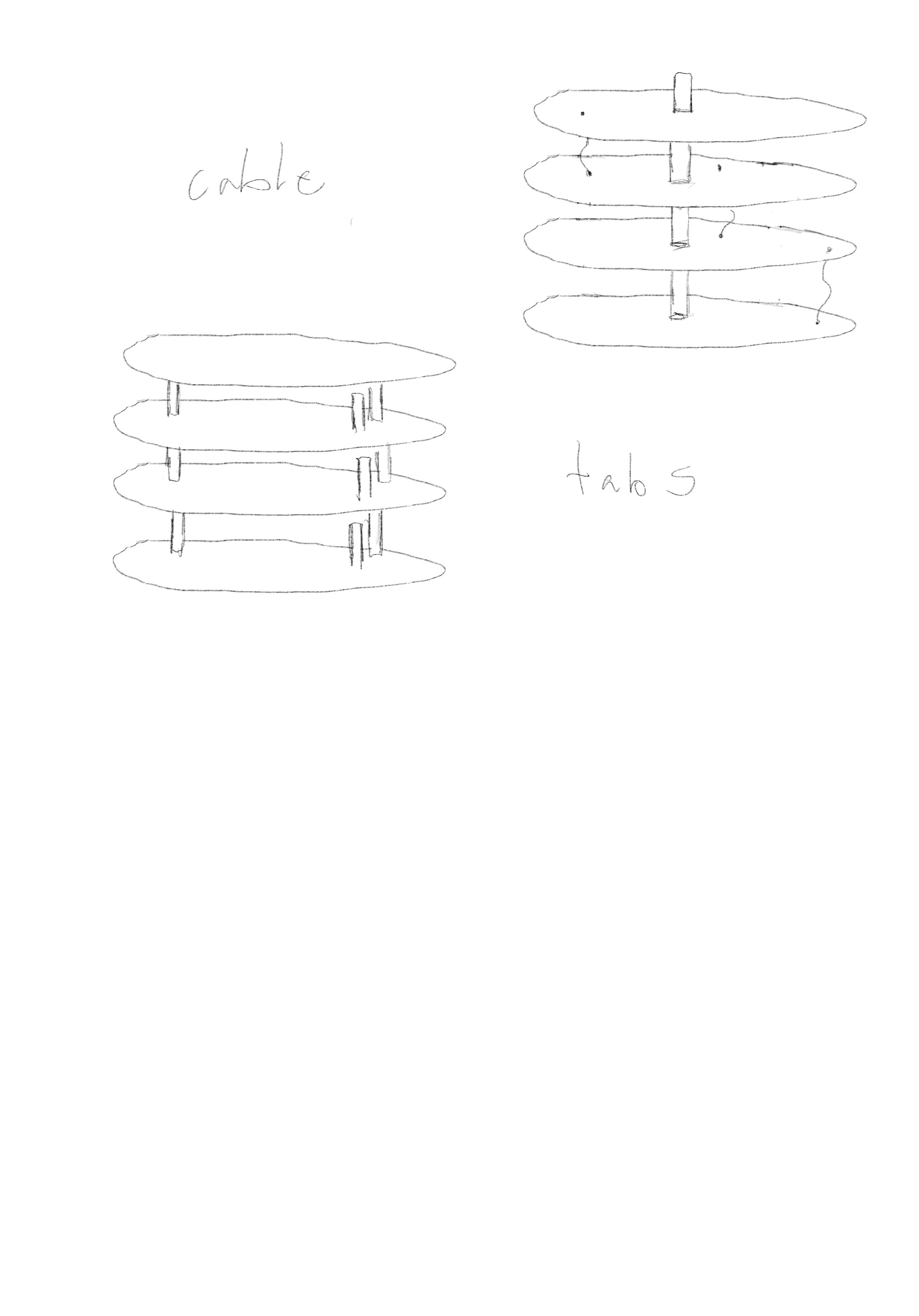 sketch tabs and wires
I then figured I needed to get some prototype going ASAP to see if it was possible.
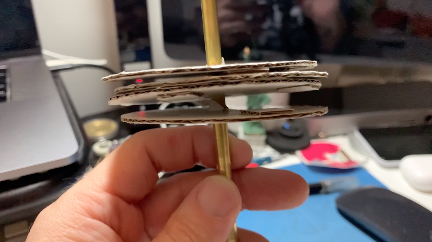 paper proto v1
 paper proto v1 gif
Once I had that, I was relatively confident that a mechanism like this could work. But weight and exactly how to fabricate it were still a question.
 proto v2
 proto v2 side gif
 proto v2 top gif
This prototype proved that the mechanism could work, and the support discs and tabs glued together could be a usable fabrication method.
But could I move the weight without breaking glass???
I ended up building this mostly IRL before I got into CAD, but I needed some help figuring out the tab placement and turned to CAD for that help. Then I got sidetracked with building an exploded version and some animations.
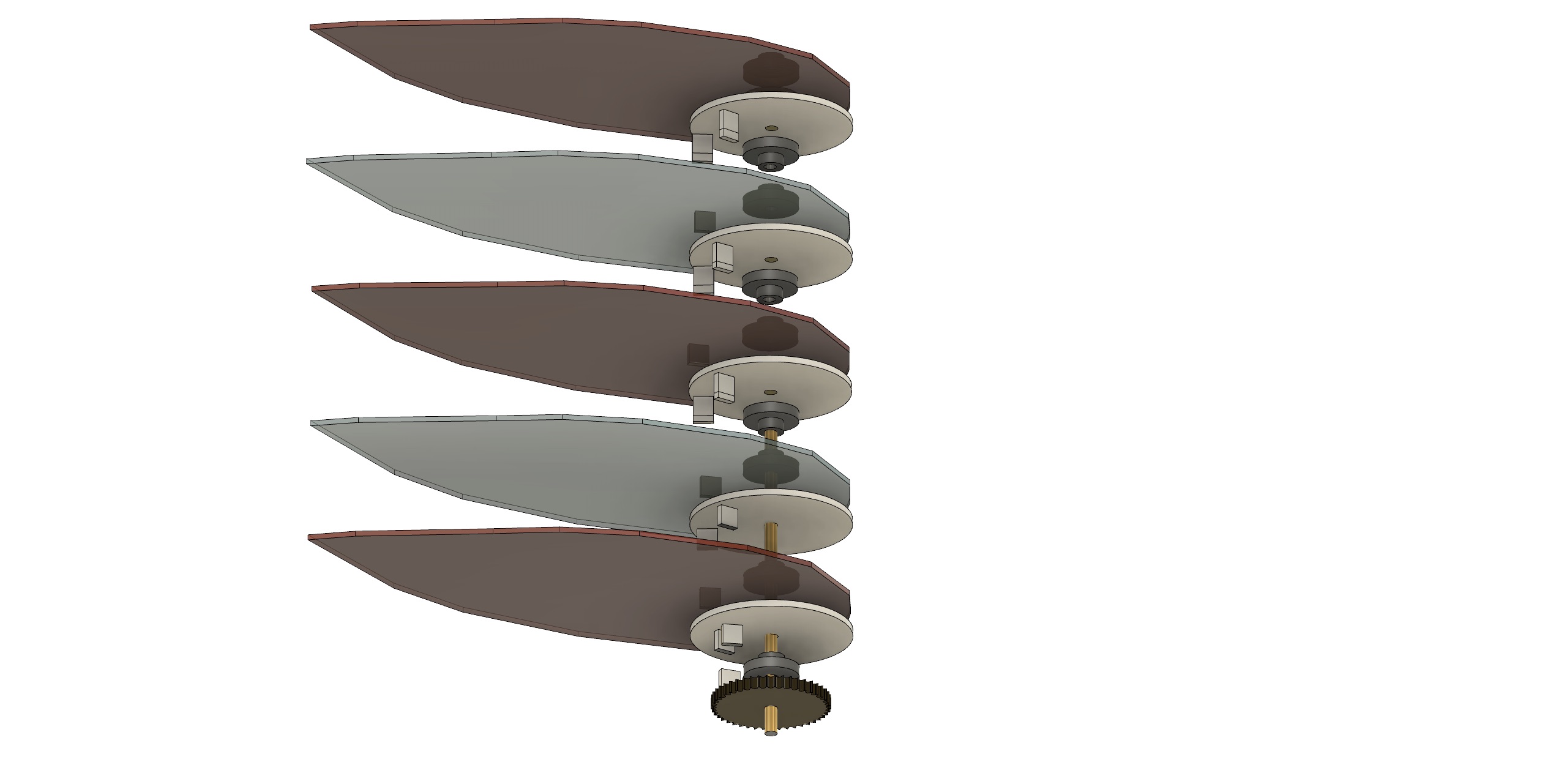 proto v3 exploded
 proto v3 lateral open gif
 proto v3 top open gif
Fabrication
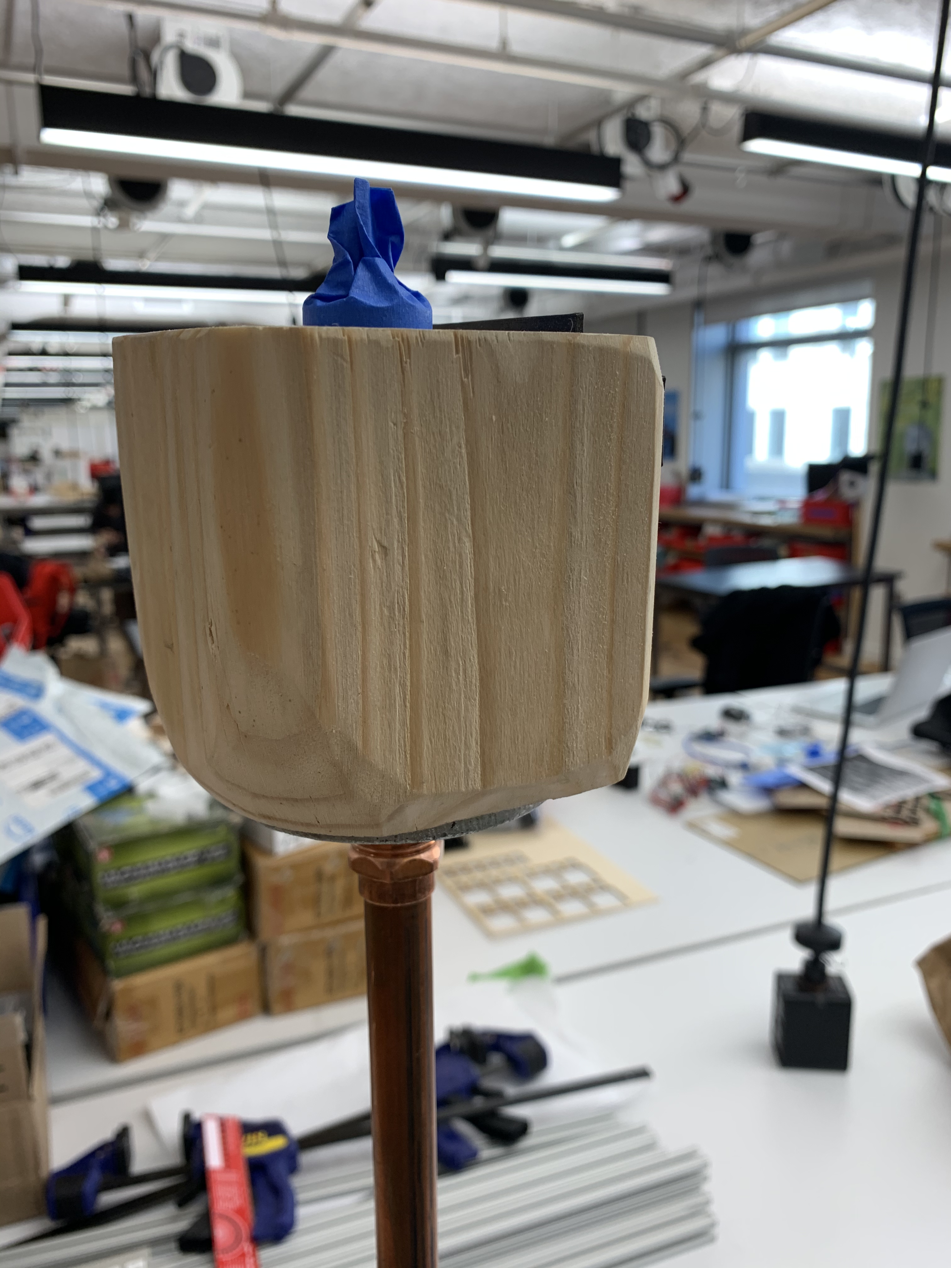
The fabrication, aside from the glass petals, was pretty straightforward. I used 4x4 wood for the base and the bottom of the flower assembly. It allowed for weight and a rigid structure.
I laser cut the support discs, tabs, and the wooden flower pot cover, as well as the leaf for the solar panel. The panel pressure fit into laser cut holes in the leaf. I 3D printed gears modeled in Vectorworks and the servo motor mount downloaded from Thingiverse.
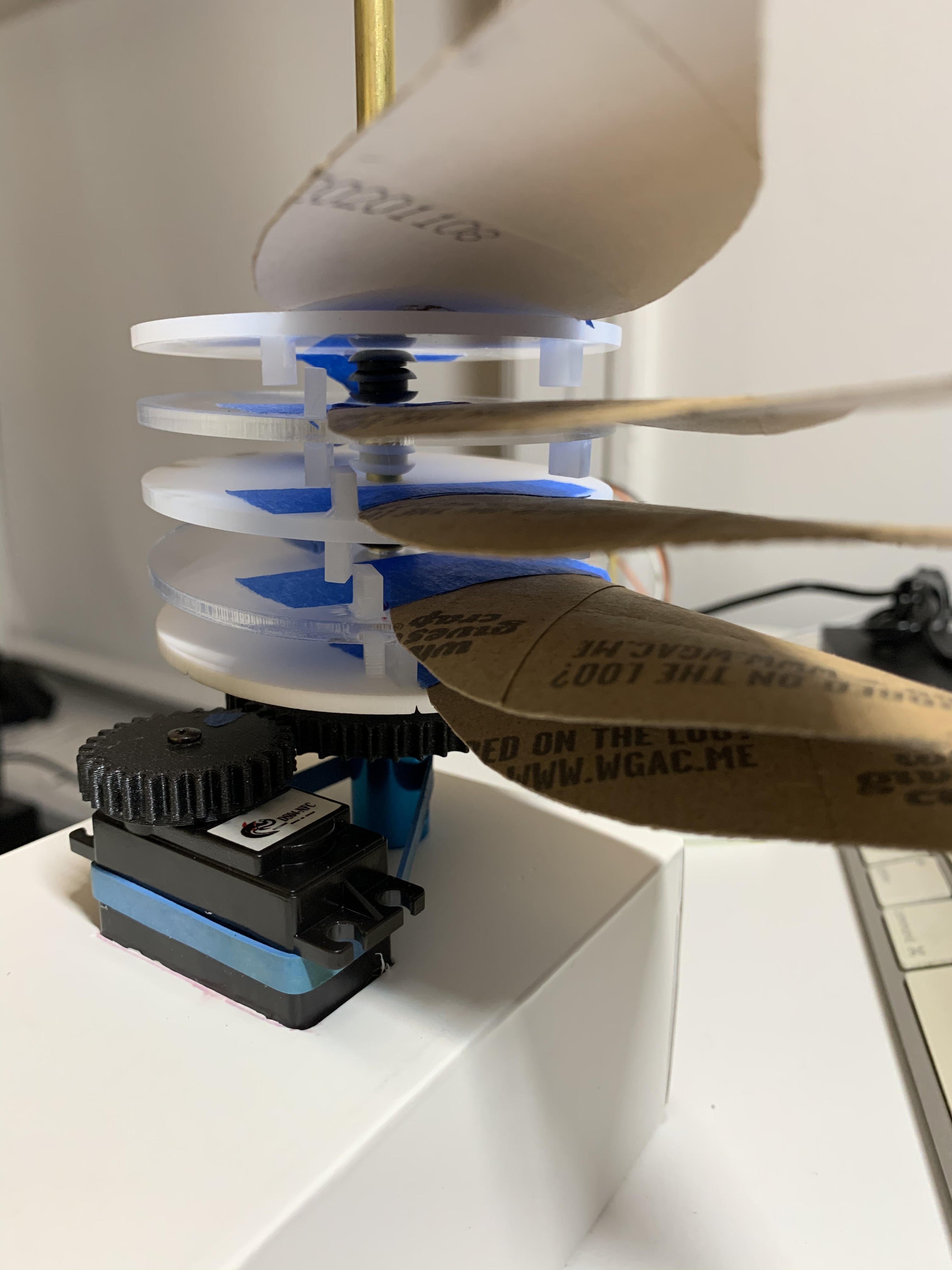
The discs and tabs adhered to the glass petals and various combinations of shaft couplers and rubber grommets were used to space them out to account for the variance of the glass surface.
A brass rod was used as the central shaft for the petals to rotate around.
 flower motor assembly base
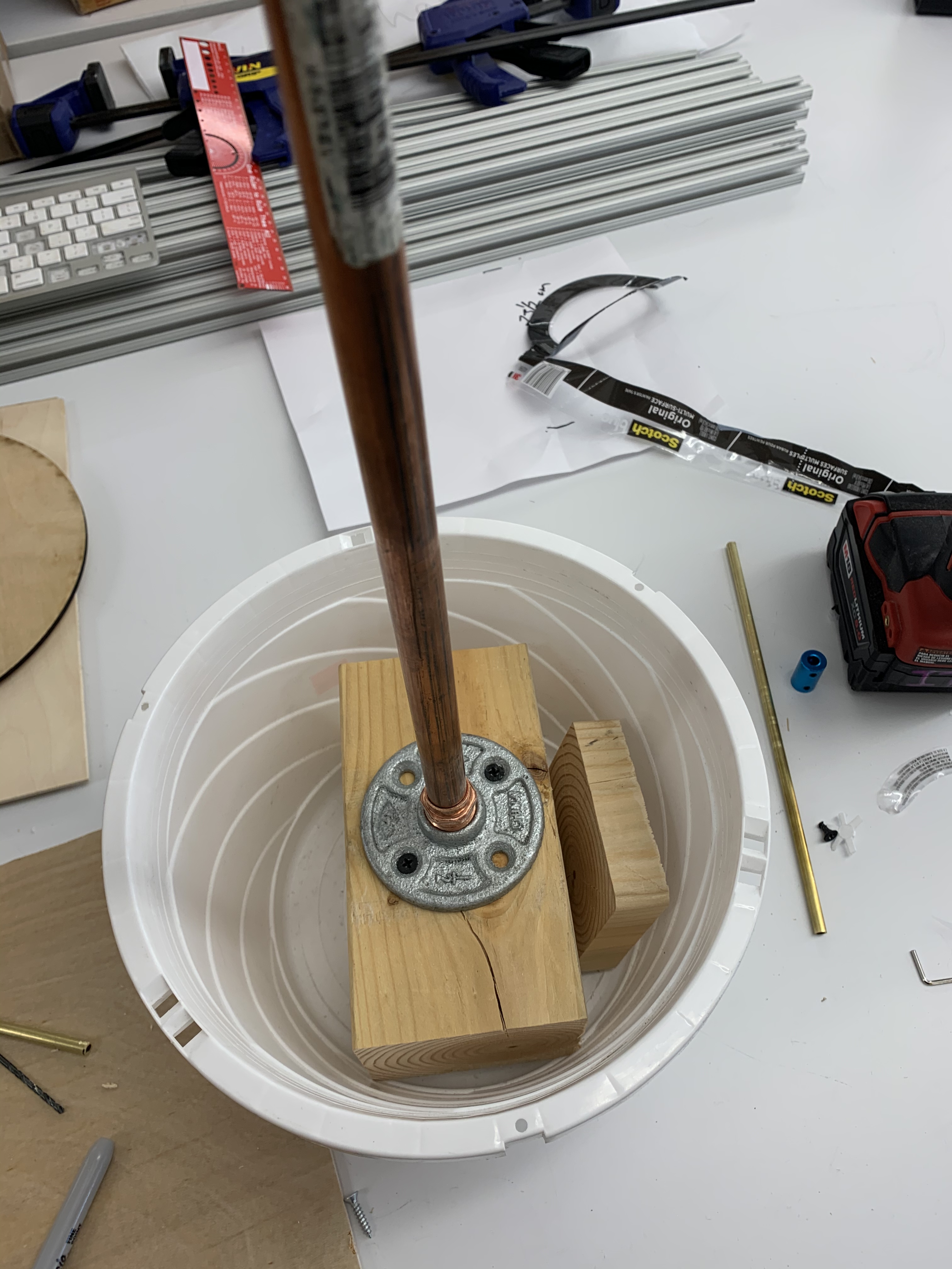 flower pot base 4x4
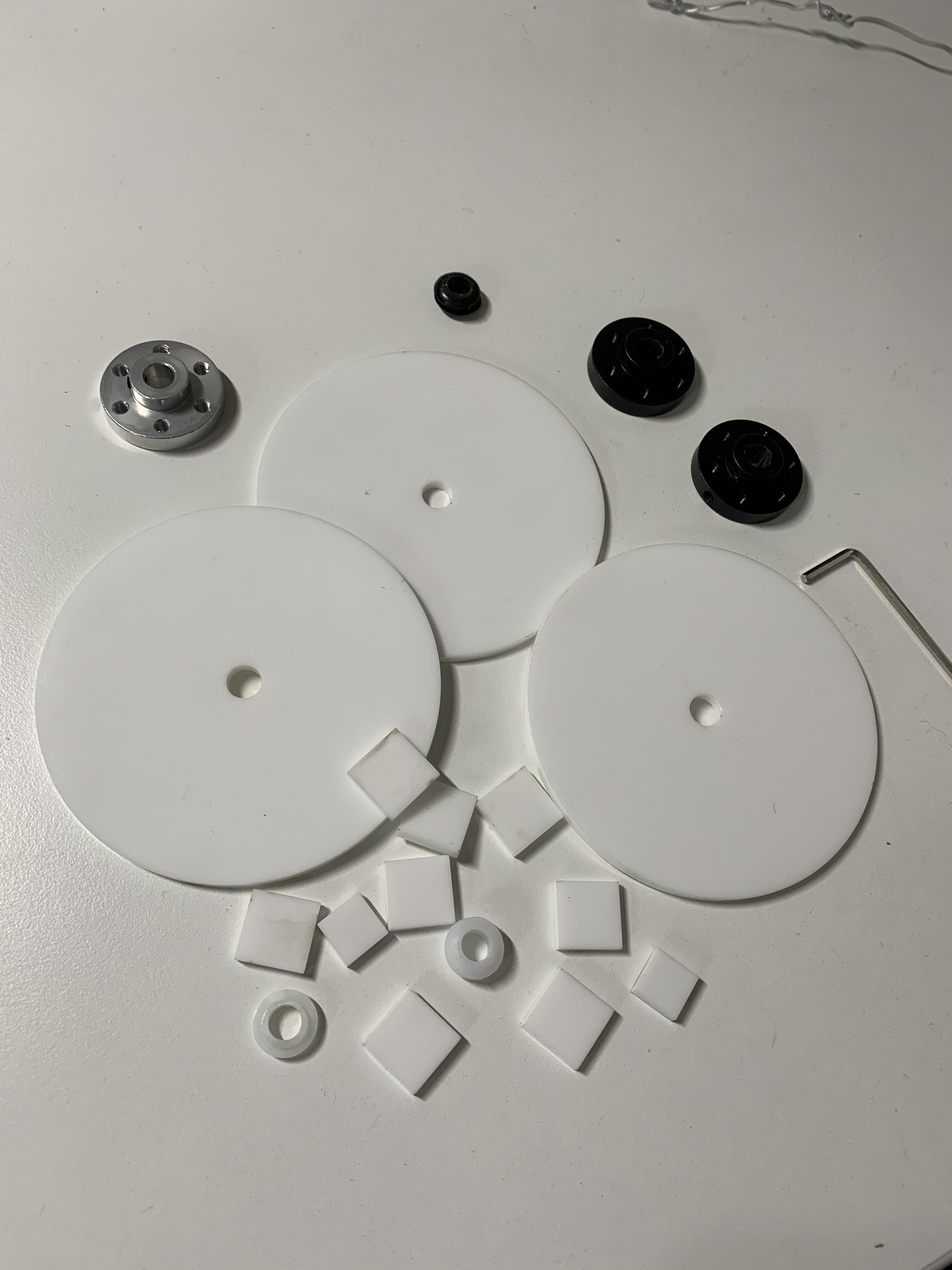 laser cut discs and tabs
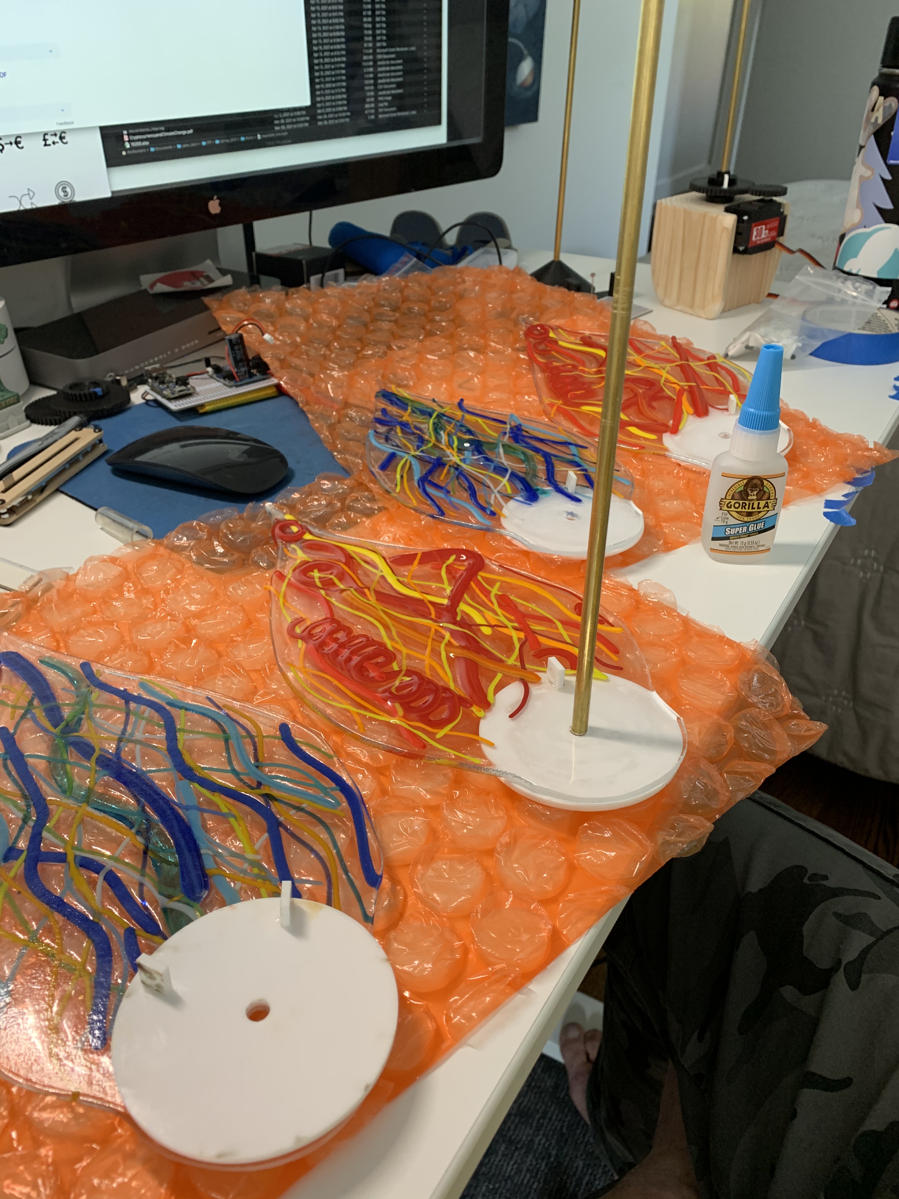 petal assembly
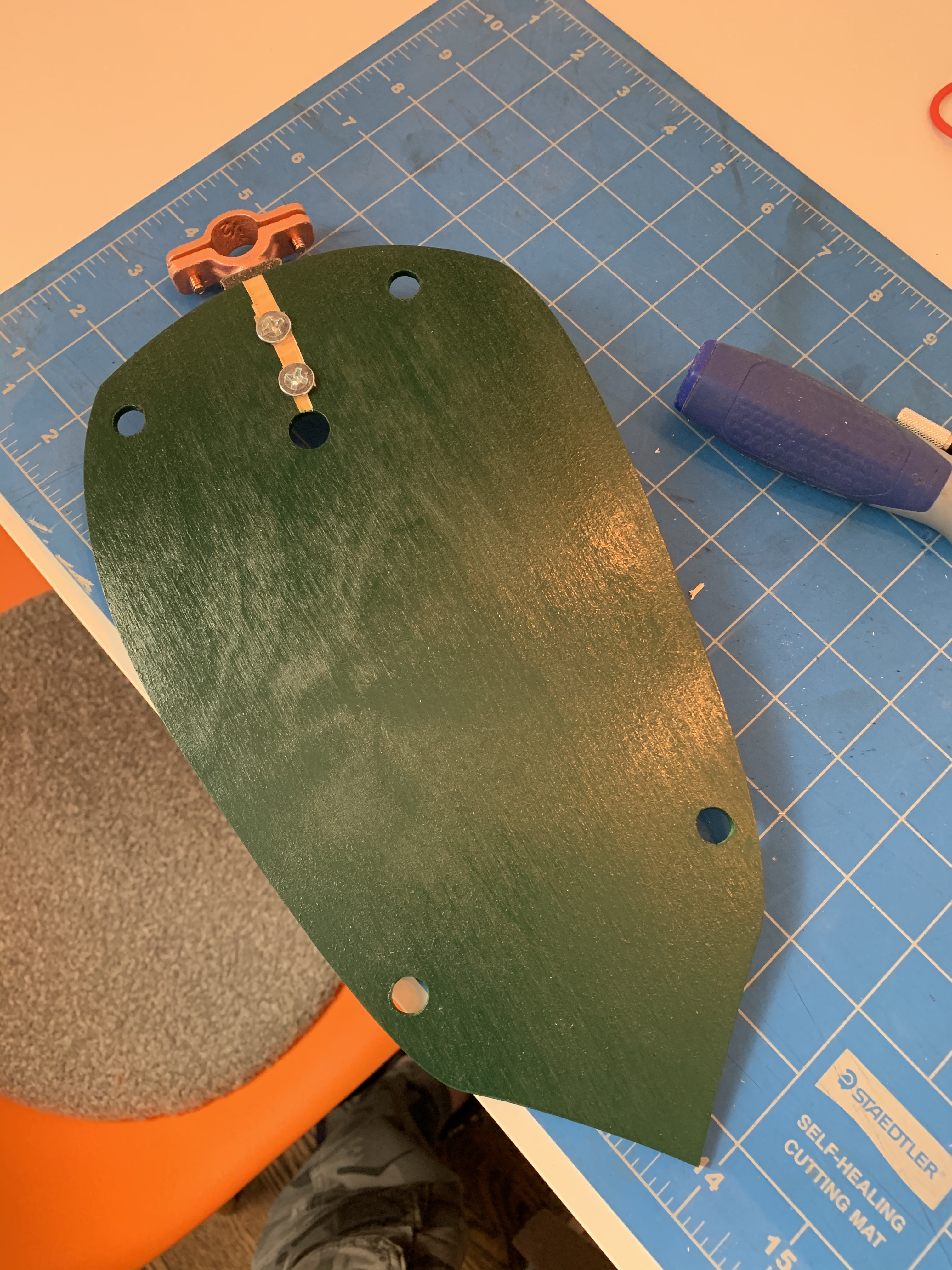 leaf w/ bracket
 petal assembly gif
The stem was a copper pipe with all wiring run internally, which was its own challenge.
Solar
Originally wanting to build my own panel with SunPower cells, I ended up moving to a adafruit panel as it simplified the circuit and power requirements.
I still plan to build out the SunPower panel, but the low voltage, high amperage greatly complicated the circuit as well as sourcing parts.
The adafruit solar panel is spec’d at 6V 3.5W.
Part of the project was to attempt to make the circuit as efficient as possible. I ended up using the Adafruit Sleepydog library, which, combined with my DFRobot Beetle board, allowed my standby amperage to be as low as 0mA. However, it was a bit higher when the circuit was fully put together.
My readings show about 7 mA / hour in standby and 35mA / hour in standby with light check mode—a combined 504 mAh a day. Which with my 2500 mAh battery should last about 5 days on a full charge.
Per the formulas on the Voltaic site, it will take about 1.37 hours to charge in optimum conditions fully; real-world took closer to 3.
I did learn a valuable lesson, always check the polarity of lipo batteries. I had an old battery that apparently had the JST cable reversed, and I ended up frying my charge controller. A new controller and battery fixed the problem.
Code
Overall the code is relatively simple. Using the 360º servo, I did need to work out the logic for my desired rotation. I basically do a pseudo-PWM and just increment the movement by 1 until I reach my chosen degree. Then send a stop signal.
The other tidbit is the snooze function. I found out the hard way that using the Beetle board, which has no reset button, it’s very easy to get stuck in a deep, deep sleep. I entered sleep mode and was unable to escape and load another sketch. I finally found that there is a reset short, which also proved challenging because my board was already soldered to a proto board. I luckily could snake a wire through a hole and complete the short reset.
Finding that also led me to a better way of just setting a delay initially to allow for loading a program before it starts the sleep sequence.
Code is here on Github
Circuit
The main circuit consists of the Beetle MC, a photo-resistor to check for light, and the servo. The solar circuit has a charge controller, charge booster, panel, and lipo battery.
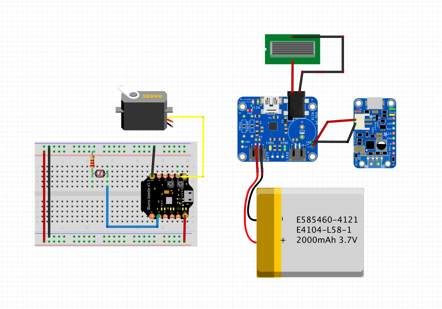 solarbloom circuit
Result
Solarbloom - an efficient solar powered kinetic sculpture, collab with @marysherwoodartglass
Overall I’m happy with the result. Figuring out the mechanism and having it actually work was the highlight of this project. Ultimately, this is a prototype for additional projects I hope to collaborate on with my mom.
Solarbloom
Bill of Materials
Photo Gallery
 IMG_5323
 IMG_5338
 IMG_5339
 IMG_5340
 IMG_5341
 IMG_5376
 IMG_5377
 IMG_5378
 IMG_5379
 IMG_5380
 assembled_charging
 chargecntrlr_charging
 chargecntrlr_charging2
 close_up
 flower_closed_exploded
 flower_w_wires_sketch
 laser_discs_tabs
 leaf_bracket
 leaf_bracket2
 leaf_bracket3
 orig_flowr_sketches
 painting_parts
 petal_assembly
 pot_access
 pot_access2
 pot_wire_mgmt
 pot_wire_mgmt2
 prefinal_assembly
 protoboard_w_beetle
 protoboard_w_chargecntrlr
 protoboard_w_chargecntrlr2
 protoboard_w_chargecntrlr_battery
 side_view
 solarbloom_circuit
 solarbloom_hdr
 solarbloom_side
 solarbloom_side2
 solarbloom_side_closeup
 solarbloom_top
 solarbloom_top2
 solarbloom_top_closeup
 tabs_v1
 tabs_v2
 tabs_wires_sketch
 top_view3
 wiring_holes
 wiring_holes2
 wiring_holes3
 wiring_holes4
 wiring_panel_plug


